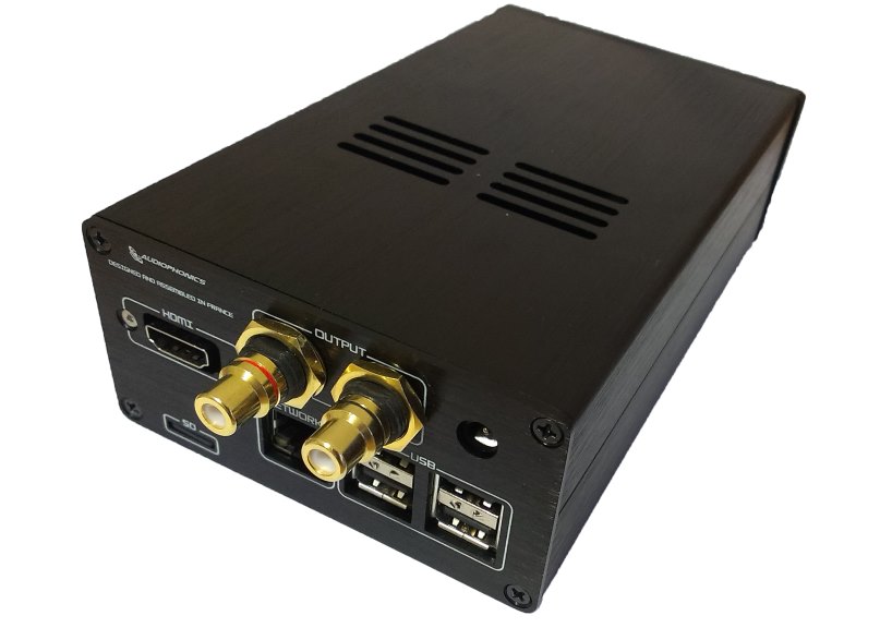
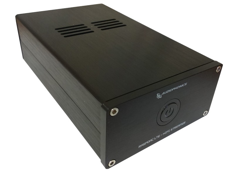
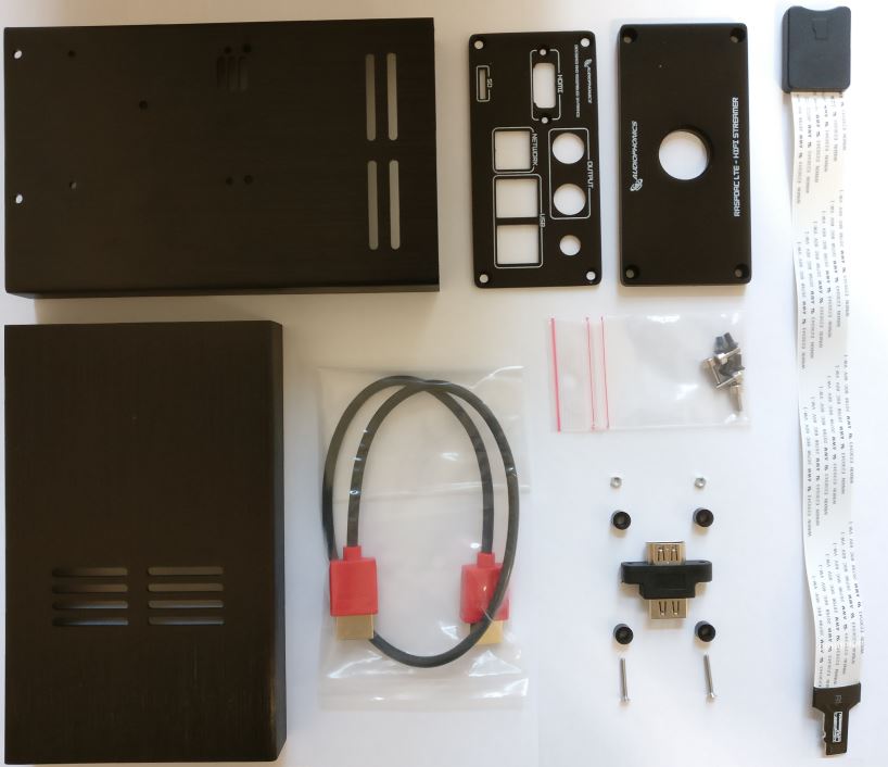
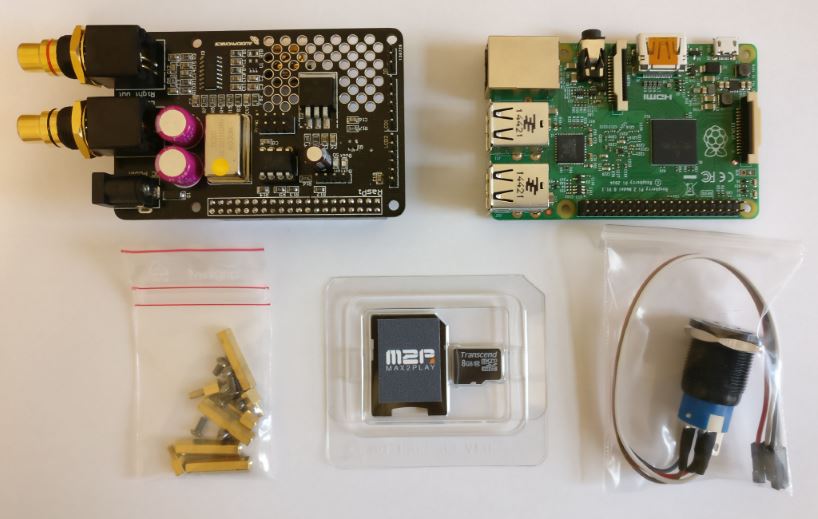
Here, we show you how to assemble the high quality aluminium case for the I-Sabre V3 (or V4) DAC. The case can be purchased here in our shop.
Attention: These instructions require a few manual adjustments of the individual parts and is thus not suitable for newcomers!
Step 1
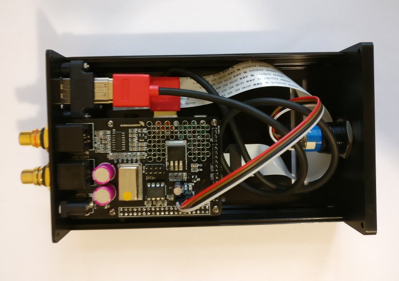
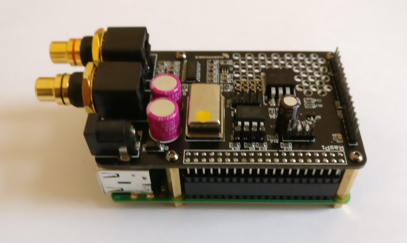
Firstly, the I-Sabre V3 (or V4) DAC is mounted on top of the Raspberry Pi. The required parts are included in the DAC’s package. The short spacer screws are mounted through the 4 holes from the bottom of the Pi. From the top, the longer spacer screws are now screwed down. Afterwards, the DAc can be stacked on top of the Raspberry Pi and affixed with 4 of the 8 screws (requires 1,5 Allen wrench). The remaining 4 screws will be used, later.
Step 3
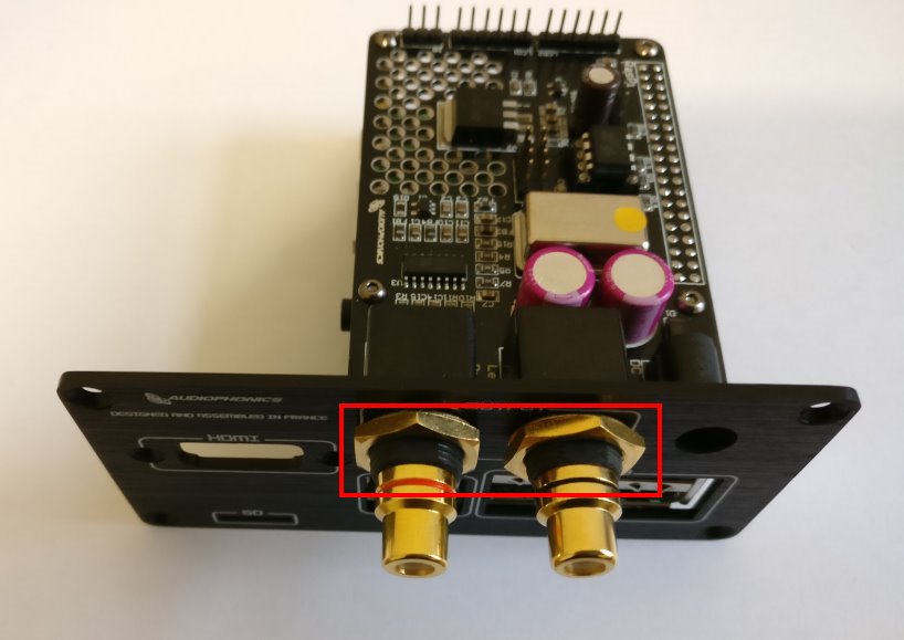
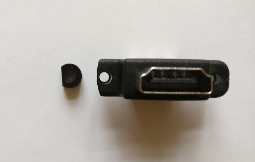
Afterwards, using a box cutter, a piece of one of the black spacers and of the side of the HDMI adapter is removed (see picture Step 4). Without this little tweak, the HDMI adapter can not be mounted together with the DAC on the back panel.
Hint:It may happen that the manufacturer includ a black hdmi cable with a already integrated socket. In this case, more than just the band protection and one side of the adapter must be removed so it fits into the case.
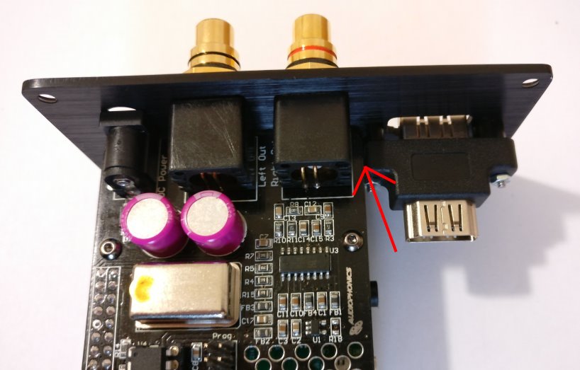
Step 4
Once everything fits, the HDMI adapter is also mounted on the back panel. For this, the long screws are put through the respective holes of the back panel from outside (printed side) and the HDMI adapter is affixed from the inside with the small nuts. The black spacers are placed between the panel and the HDMI adapter on top of the screws.
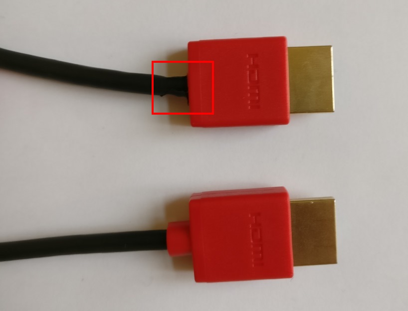
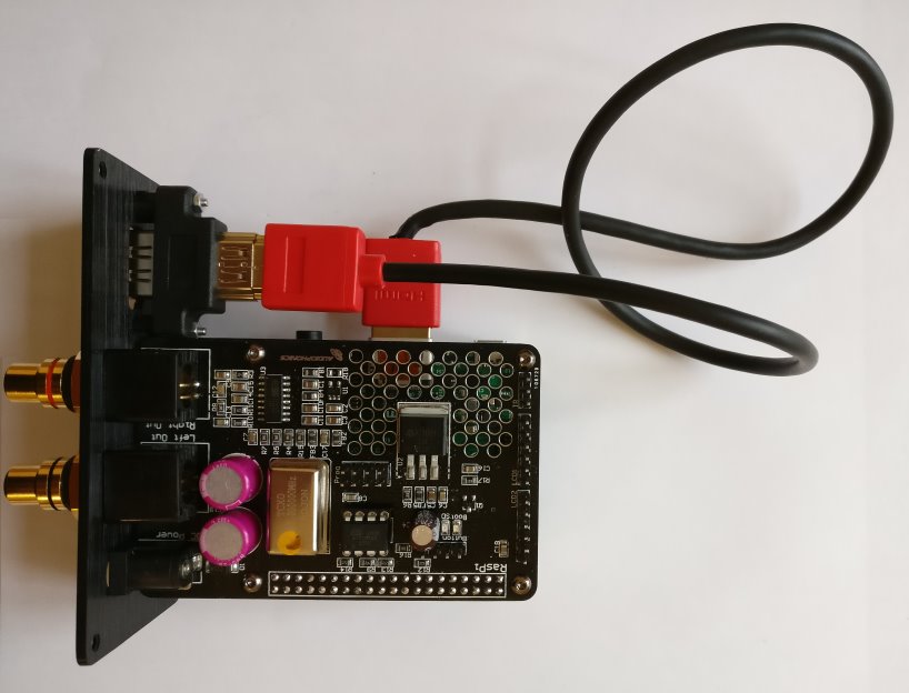
Step 5
The HDMI cable also requires a small adjustment to be incorporated. The red plastic end of one of the two plugs has to be removed cautiously with the box cutter. Afterwards, the cable is connected to the adapter and the Raspberry Pi. Please make sure to connect the cable end with the removed plastic part to the Pi.
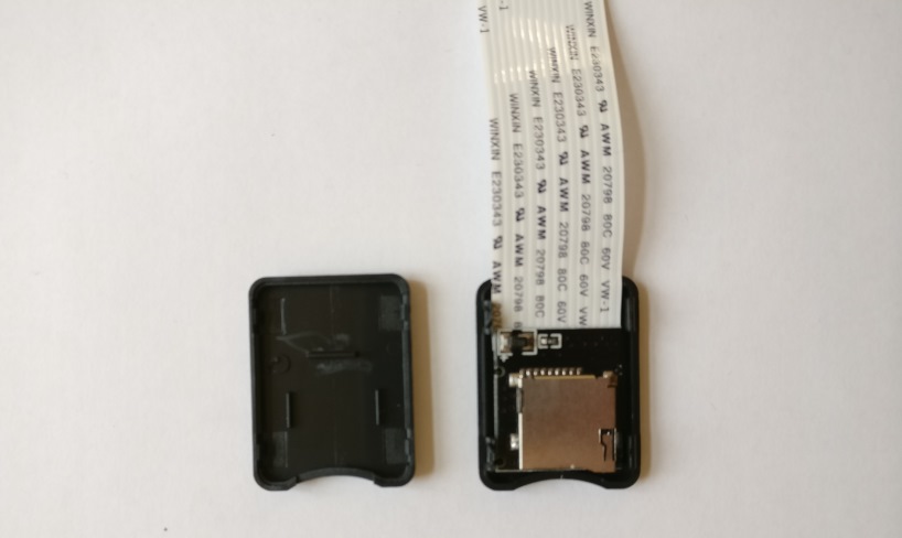
Step 6
In the next step, the plastic cover of the SD card adapter cable is cautiously removed and subsequently not needed anymore.
Step 7
The side of the SD card adapter cable, which was just stripped of its plastic cover, is now mounted on the inside of the case’s bottom (the half with the holes in it) with the black boardside upwards (see picture) using glue or double-sided tape. For this, the front panel of the case should be placed next to it to test the SD card slot’s opening and it’s parallel connection to the adapter.
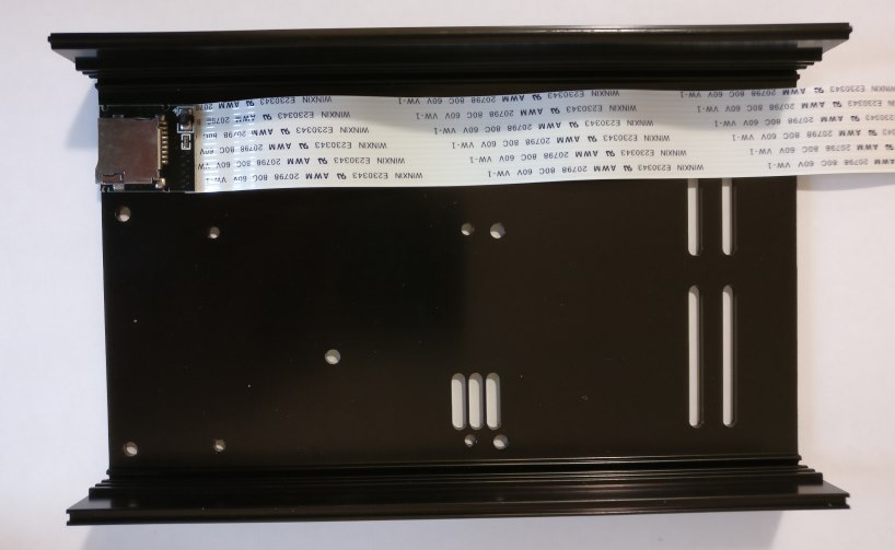
Step 8
If you used glue to affix the adapter, please let it dry first. Afterwards, the front panel can be mounted with the previously altered parts (thanks to the modified HDMI cable, everything should fit nicely now) and the other end of the SD card adapter cable can be inserted in the SD card slot of the Raspberry Pi.
Step 9
The front panel is now affixed with the two black case screws as pictured. With the remaining 4 screws from step 1, the Raspberry Pi is now also fixed to the bottom of the case. If the holes do not align with the spacers on the bottom of the Pi, we recommend using not all but at least 2 screws.
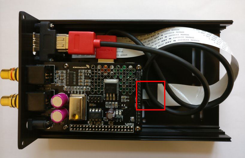
Step 12
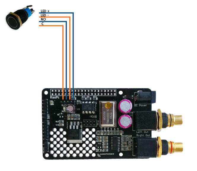
The back panel is now mounted with the silver screws (Allen wrench 2,5 required). To make sure the top panel of the case can be mounted, the pins of the DAC, on which the button is connected, must be bent slightly.
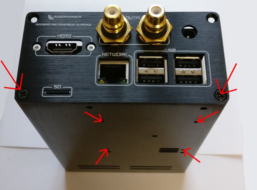
If everything fits, the top panel is also screwed tight using the rest of the screws. Done!