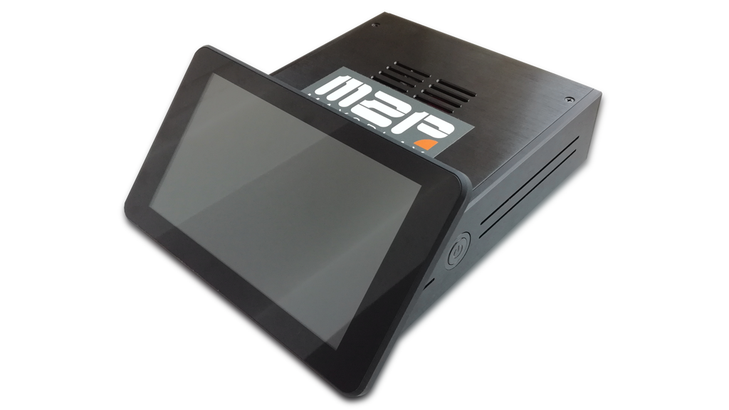
Here, we will detail the assembly of the RaspTouch. The corresponding bundle for this setup can be found in our shop. If you already own these parts, the case can also be bought separately.
Please adhere to these instructions to prevent damage to the devices. This manual explains step by step the assembly of the RaspTouch with all necessary components.
!Attention! This bundle is intended to be used with the Max2Play 7 inch Touchdisplay image. The download link can be found on our download page.
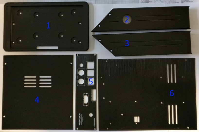
Delivery Scope
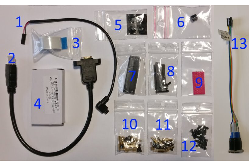
…and the following accessories:
1: Micro-USB adapter or Jumper cable
2: HDMI port
3: display cable
4: SD card port
5: 4 rubber feet
6: sealing nipple
7: mounting material for the display holder
8: mounting for SD card port (2 larger, 2 smaller screws) and connector
9: rubber isolation piece for heat dissipation
10: Package with mounting material for the Raspberry Pi (6 nuts, 6 spacers, 6 small screws, 2 slightly larger screws, a metal insulation piece, a plastic ring)
11: Package with mounting material for the display board (4 spacers, 4 nuts, 4 screws)
12: 22 M3 (4mm – PH2 compatible) and 4 silver screws for the case
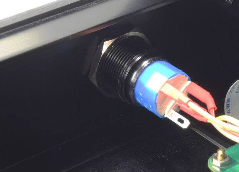
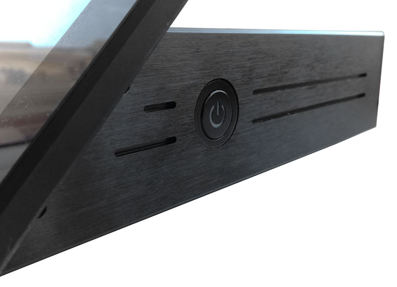
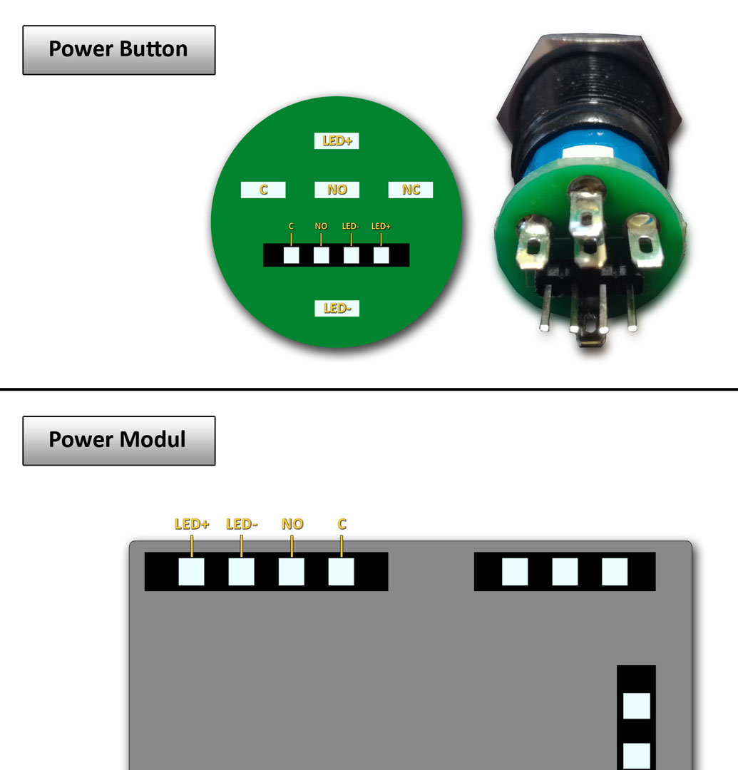
13: Power Button with pre-mounted cables
Additionally required:
- 7″ touch display with spacers
- Raspberry Pi 3
- DAC or Digi sound card with freely usable GPIO17 and GPIO22
- Depending on the selected sound card, additional adapter cables if necessary
- SD card with pre-installed Max2Play
- Power Management Module (with thermal paste)
- Power supply with at least 7V / 3A
Selection of the sound card
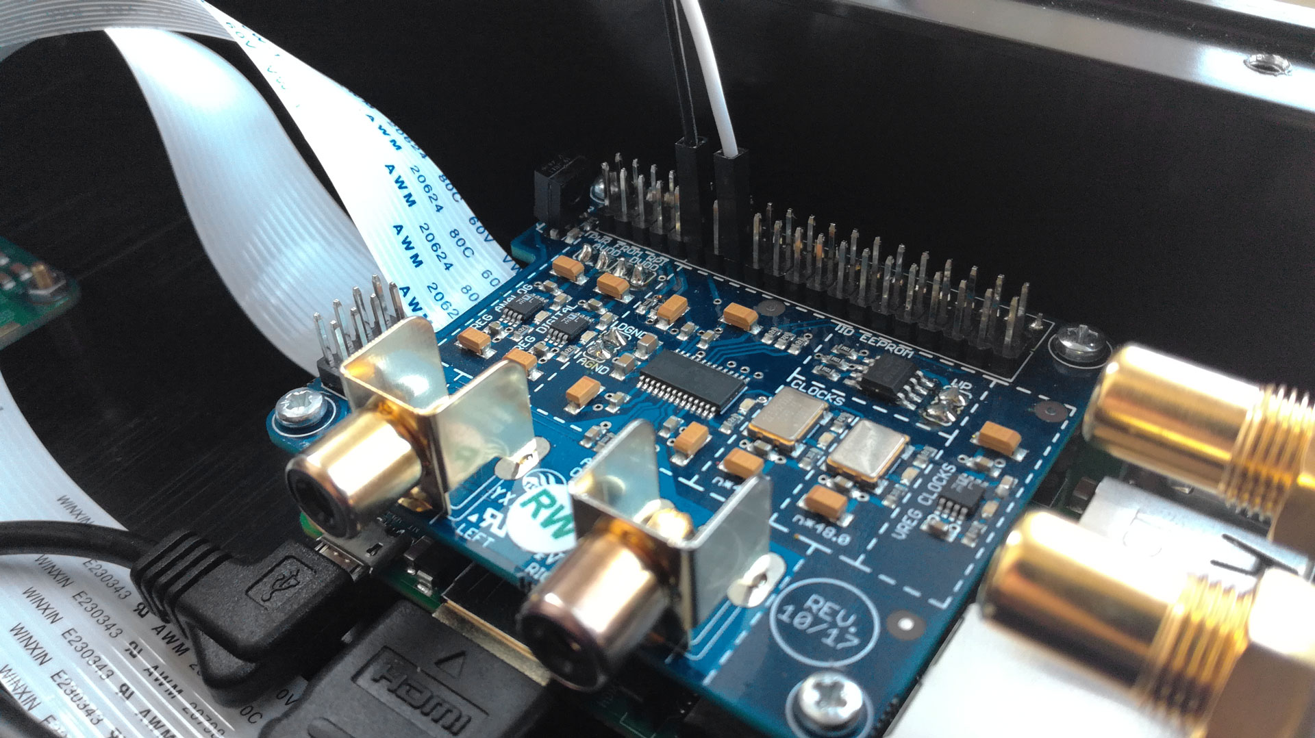
This bundle is compatible with common HAT sound cards. To use the boot and shutdown feature of the power button, the sound card must provide GPIOs 17 and 22 for free use. Some cards, such as the Allo BOSS DAC or the AroioDAC, already have soldered pins for using the GPIOs. For cards where this is not the case (such as the HiFiBerry DAC+), the corresponding pins must be soldered by oneself. For the HiFiBerry DAC+ Pro and Digi+ Pro we offer versions with pre-soldered GPIO-bar.
Further below is shown, where to find the needed GPIOs on different sound cards.
Step 1
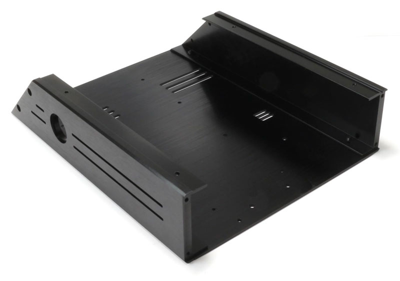
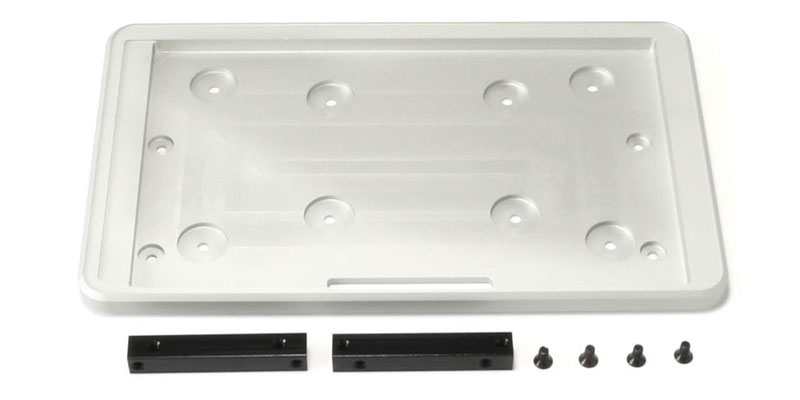
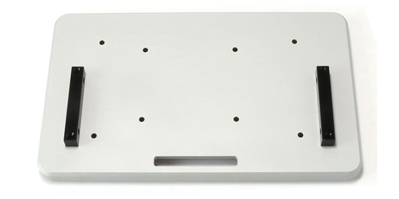
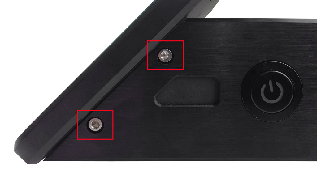
The first step entails affixing the lateral plates with the bottom plate. Take the necessary plates (side and bottom plates) and 4 of the M3 (4mm) screws from the package with the screws for the case. Make sure that the bottom plate is installed correctly. The picture serves as an orientation.
Step 2.1
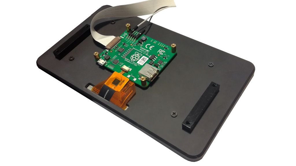
You need to remove the board of the 7 inch touch display. To do so, first remove the spacers and then loosen the board. The original spacers of the display are not part of the further assembly. They are replaced by golden spacers from the delivery scope, when the board is installed in the case (step 6).
Step 3
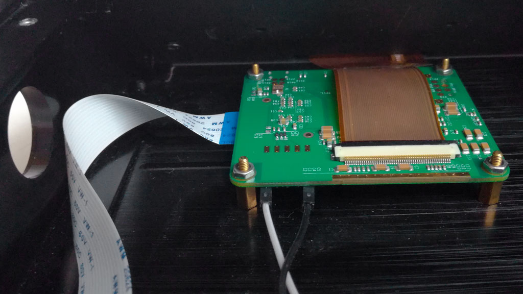
Use the display bracket and feed the flat ribbon cable from the front though the recess. Then place the touch display. Fix the display with four M3 (4mm) screws. Then both flat ribbon cables can be connected with the board of the display again.
Hint: The display board will not be fixed to the display backside, but to the case of the RaspTouch itself. This will be done in the next step.
The display cable from the delivery scope has to be affixed to the side of the plate. The other end of the cable will be connected to the Raspberry Pi later.
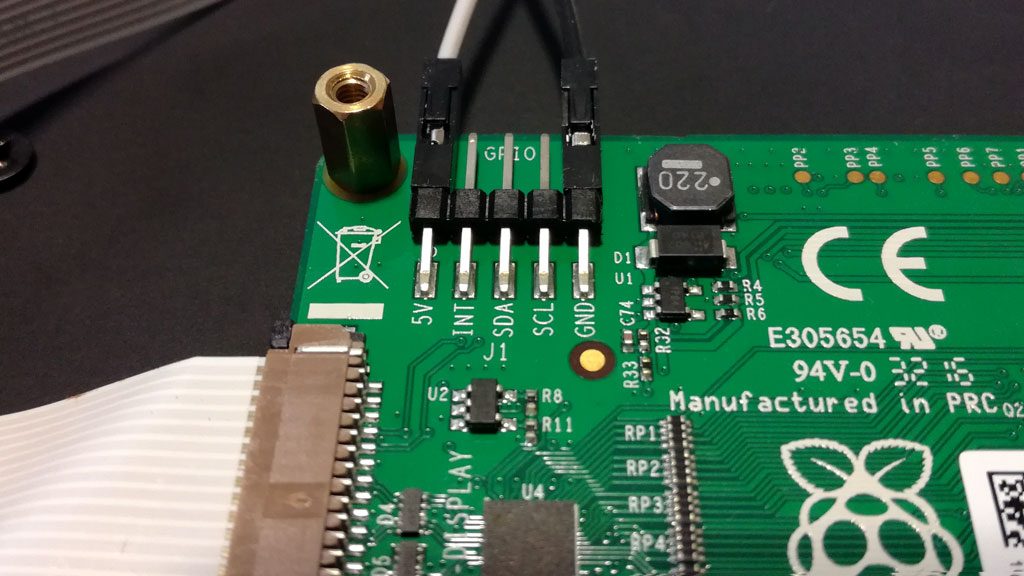
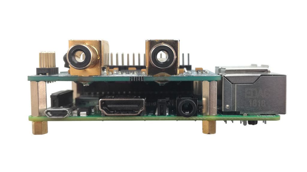
Display Board Connection
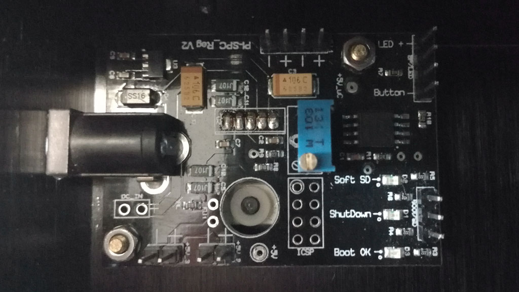
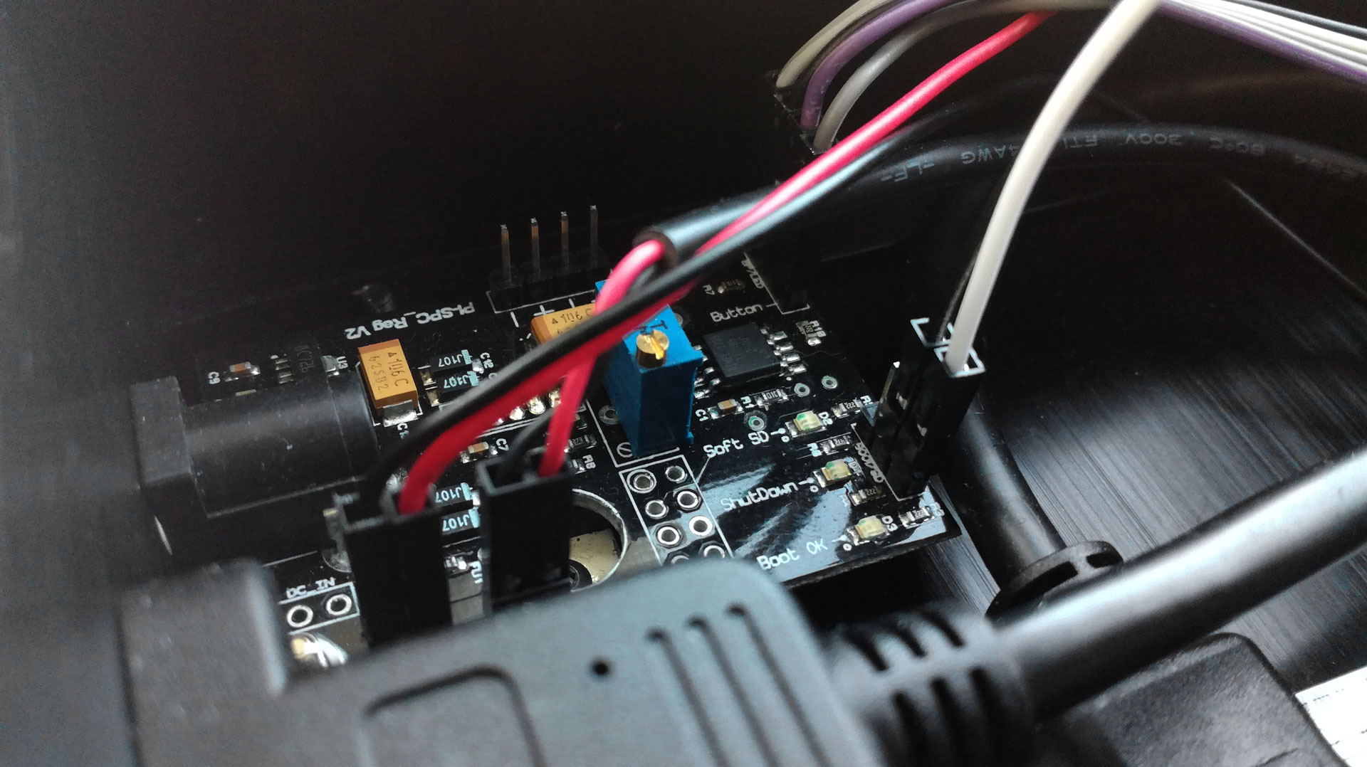
The display board is no longer connected to the Power Management Module (PMM) via a micro USB jumper cable. Please use two of the supplied jumper cables and plug them into the pins labeled „5V“ and „GND“ of the display board. Later, these are connected to the designated pins (5V to „+“ and GND to „-“ ) of the PMM.

Step 4
Now the display board can be attached to the bottom plate. You need four M2.5 (13mm) spacers (gold-plated), four of the bigger nuts and four of the M2.5 (4mm) screws from the package with the mounting material for the display board.
Add the spacers to the display board and fix them with the nuts. Now you can feed the screws from the outside through the bottom plate into the case and fix the display board to the floor plate.
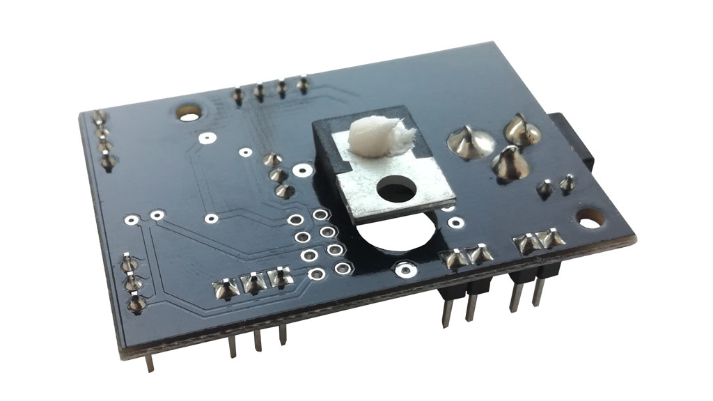
Step 7
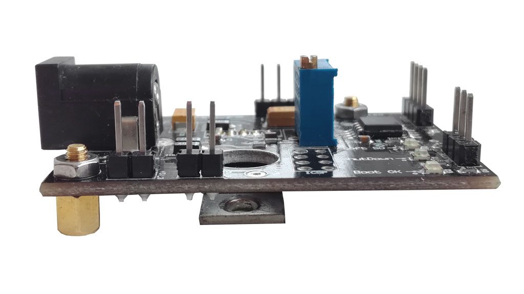
Next, screw the power management module into the back right corner of the case. 
Use two of the small black body screws and two of the smaller spacers and nuts. Take the picture for reference.
Optional: To fix the PMM in the middle you can use one of the two larger body screws as well as the plastic ring from packet 10 (or alternatively your own suitable nut).

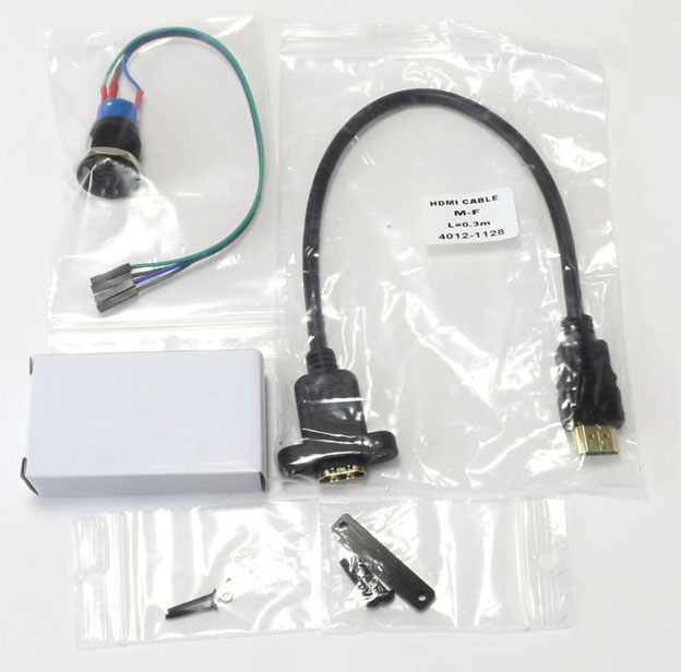
Step 8.1
Now the components from this picture are required.
- Power Button with presoldered cables
- HDMI port
- SD card port
- fixture for SD card port (metal plate with 2 holes and the two long screws from the delivery scope number 8)
- mounting material for the HDMI port (the two long black screws and the two small nuts from the package with the mounting material for the display board)
Step 8.2
First the SD card port is attached. Simply feed the end of the SD card port through to the matching recess on the backside. The SD card port is assembled with the delivered retaining plate. The attachment will be done within the case and onto the SD card connectors. Both M1.5 (12mm) (round head) screws will then be screwed through the bottom of the floor plate into the recessed part.
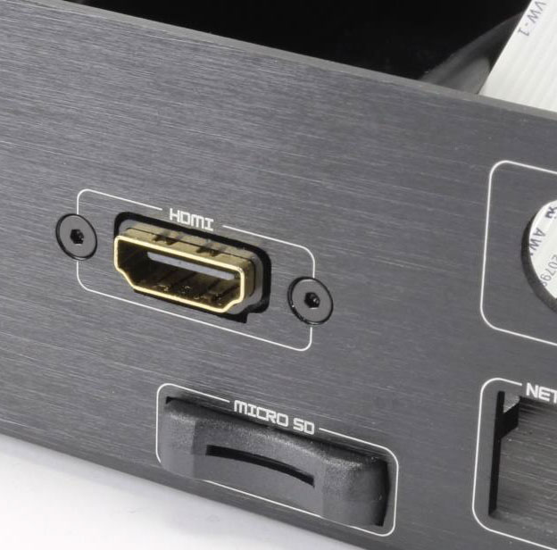
Step 8.3
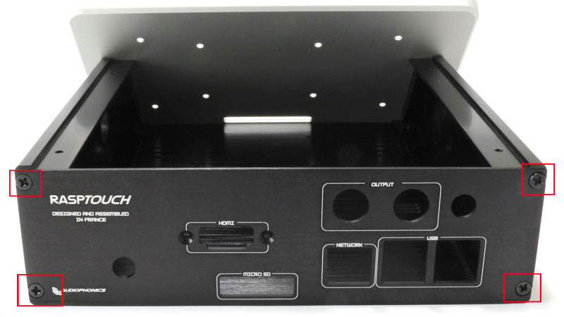
Now mount the HDMI port as follows:
Feed the end of the HDMI port through to the matching recess on the backside and fix the HDMI port to the case with the two long M2 (16mm) countersunk head screws and the two nuts. The screws will be applied from the outside of the case and the rubber-end of the HDMI connector and fastened with the two nuts from the inside.
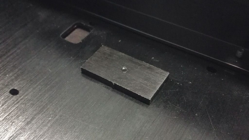
Step 10
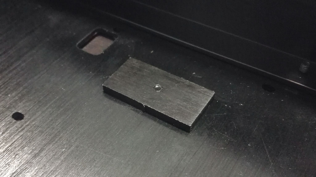
In this step the rubber isolation piece for heat dissipation needs to be applied on the case. Simply mount the supplied metal plate with the screw from the delivery scope number 8 to the spot where the Raspberry Pi will later be connected. The screw is then inserted from below through the corresponding hole in the bottom plate of the case and screwed into the metal plate. Then place the rubber isolation piece (or heat conduction paste) on it.
Hint: To find the right spot of the metal plate, the image should serve as orientation. A corresponding hole can be found in the bottom plate. Alternatively, shortly place the Raspberry Pi with the connectors on the corresponding recesses on the back panel. The plate with the rubber isolation piece should be applied below the processor of the Raspberry Pi.

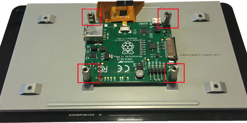
Step 11.1
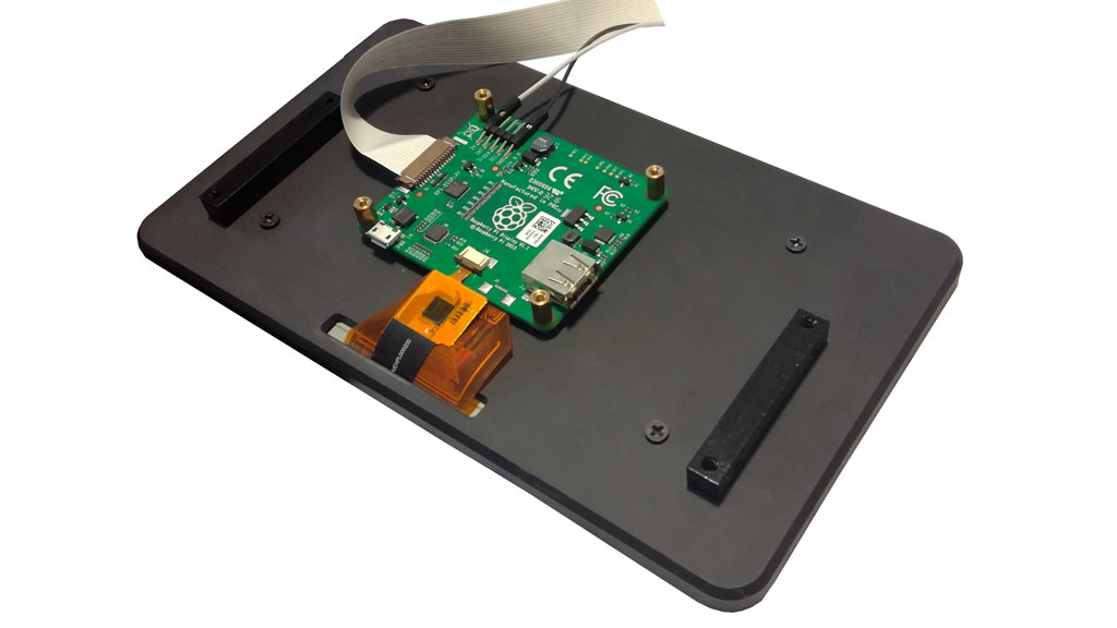
Now the sound card (in this example the AroioDAC) is attached to the Raspberry Pi. The required parts are included in the package of mounting material for sound card and the Raspberry Pi. First, the short spacer screws are inserted through the 4 holes of the Raspberry Pi from below. From above, the long spacers are now screwed onto them. Now the sound card can be plugged onto the Raspberry Pi and fixed with the appropriate screws from above.

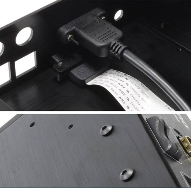
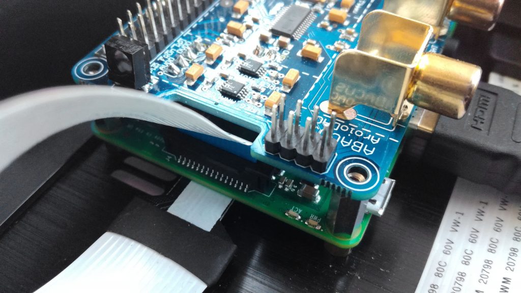
Step 11.2
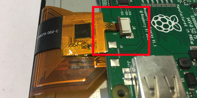
In this step the flat ribbon cable of the SD card ports and the display board as well as the HDMI cable will be connected to the Raspberry Pi.
Stick the connection cable of the display to the provided port (see picture) and fix it there. The blue side of the cable should point to the outside of the board.
The Micro SD extension should snap into the bottom of the board (see picture).

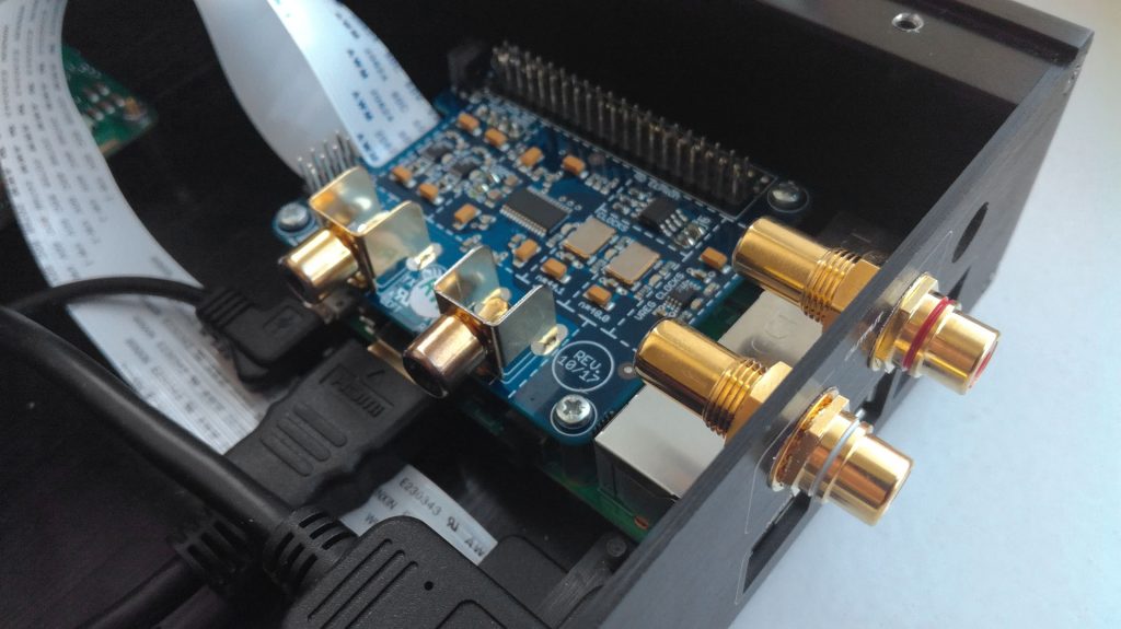
Step 11.3
With 4 of the small black case screws, the Raspberry Pi is fixed to the bottom of the case. If the drill holes in the case do not close with the spacer screws on the bottom of the Pi, we recommend using not all, but at least 2 screws.
Note: As already mentioned, the rubber isolation piece (or heat conduction paste) should be applied below the processor of the Raspberry Pi!
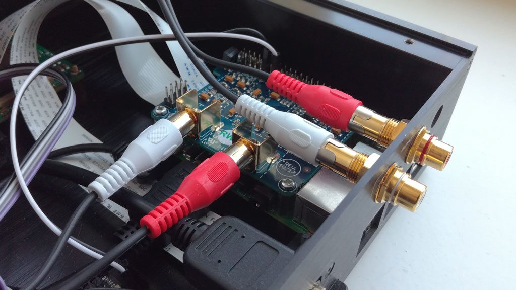
You can now also attach the two golden RCA adapters to the case as shown in the picture. Use the nut for fixation.*
*With some sound cards, it may be necessary to attach the adapters to the case the other way round.
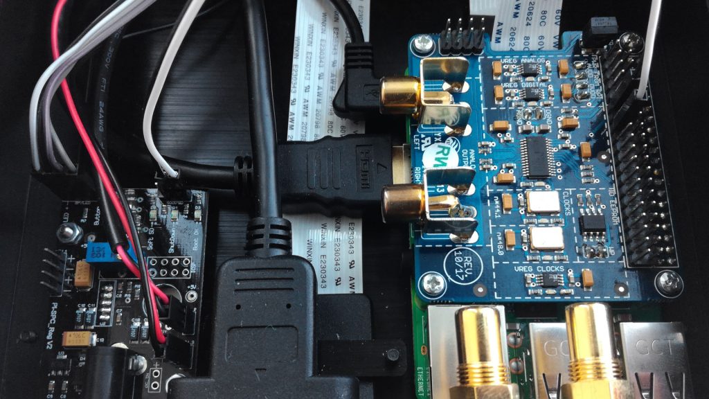
Step 12
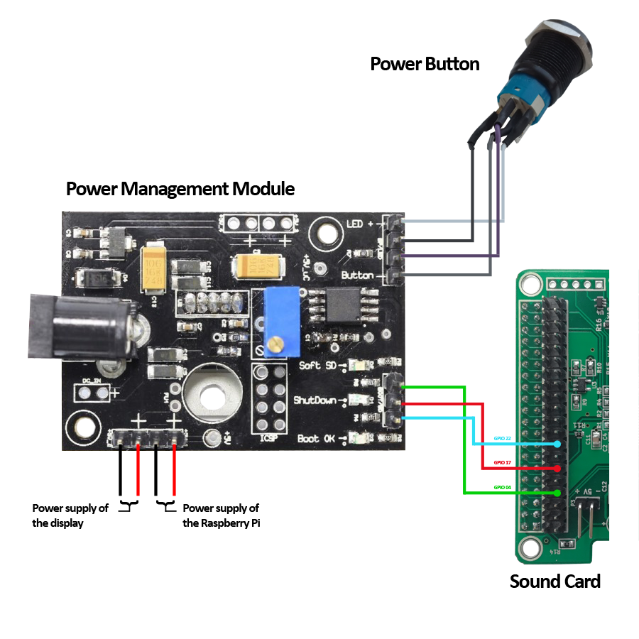
In this step the jumper cables of the display board and the power button are connected to the power management module. Furthermore, the USB cable to power the Pi and the jumper cable for clean startup and shutdown are now required (GPIO17 and 22). Also missing is the RCA cable to connect the adapter on the case with the ports of the sound card.
When connecting, follow the pictures and the schemes further below.
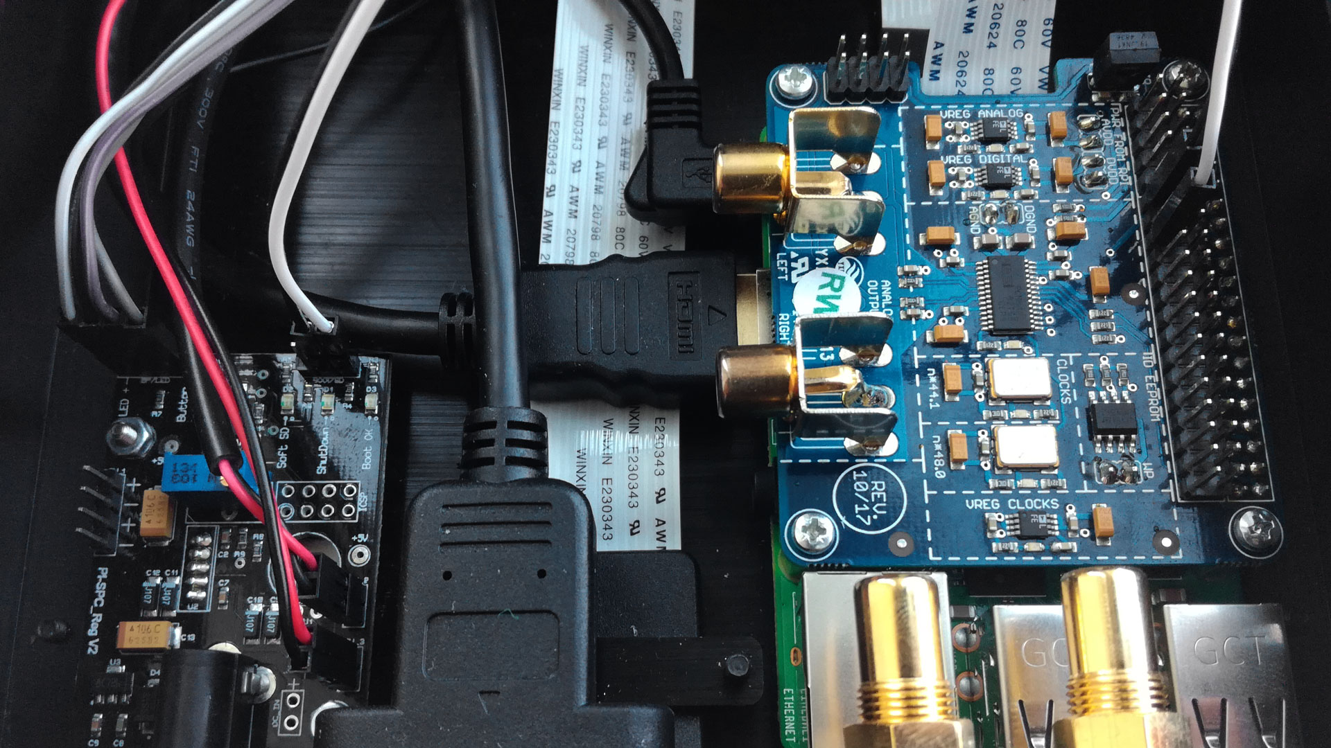

Note: Depending on the selected sound card, it may be necessary to apply some pressure to connect the RCA cable (e.g. because the HDMI port is in the way). In this case, be careful not to damage the connectors on the sound card.
The right Max2Play Image
Attention! To ensure proper operation of the system, please use the optimized Max2Play stretch image for the 7″ touch display. (if necessary update to the latest version via web interface)
Step 13
Finally the cover plate can be fixed on top. Use the remaining 4 M3 (4mm) case screws and the top plate. Slide the plate carefully over the case. Now the plate can be fixed.
Then the SD card (optionally with Max2Play preinstalled) can be plugged into the designated port.
Connect the device with the power supply and push the power button. The system now boots and the touch screen and Max2Play are ready to be used.
Step 14
In order for the power button to work properly and the whole system to be powered up and down cleanly in the future, the Audiophonics plugin must be installed after starting Max2Play. This is necessary regardless of the sound card installed!
Click on the installation button for the „Power Button“ in the advanced settings in the Audiophonics Plugin and set a checkmark for Autostart. After a restart the button is ready for use.
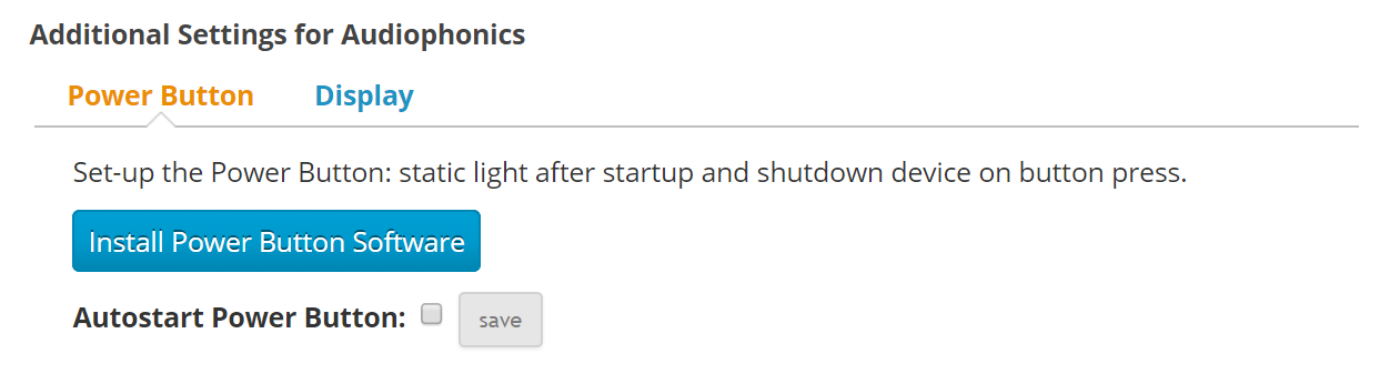
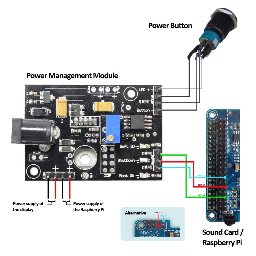
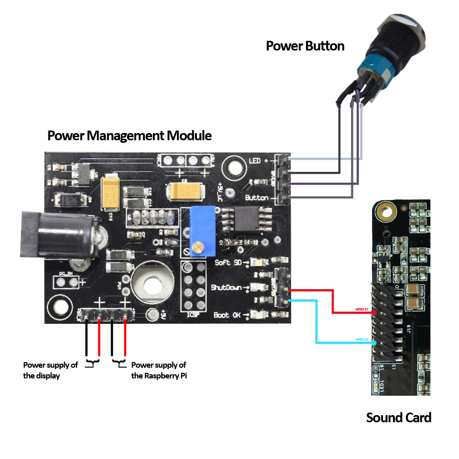
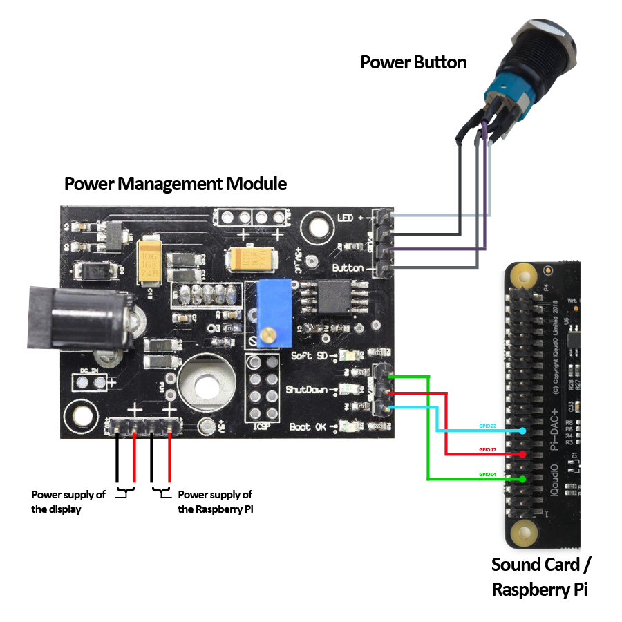
How to connect the PMM with different sound cards
Note: To use the boot and shutdown feature of the power button, the sound card must provide GPIOs 17 and 22 for free use. Some cards, such as the Allo BOSS DAC or the AroioDAC, have already soldered pins for using the GPIOs. For cards where this is not the case (such as the HiFiBerry DAC +), the corresponding pins must be soldered by oneself.
Please make sure that the GPIO17 and GPIO22 for sound cards which are not listed here are not in use.

