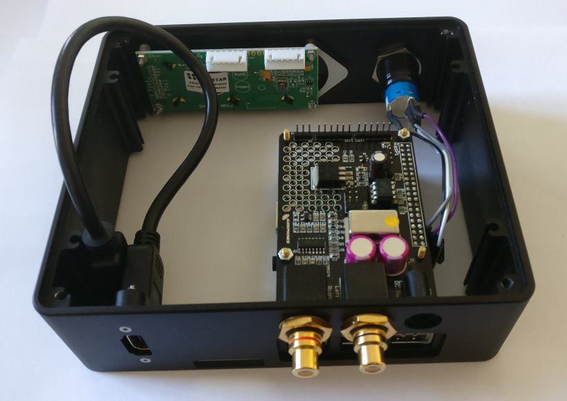
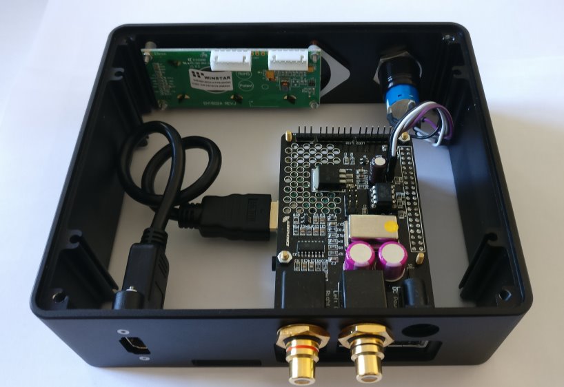
Here, we will explain how to assemble the RaspDAC case. You can find the bundle with all necessary pieces in our shop.
Please, follow this instruction strictly to prevent any damage to your devices. On the bottom of this page you can find a video by Audiophonics on how to assemble the RaspDAC with OLED display. The video is French, but has English subtitles. And since you can visually follow the steps quite easily, it is a good supplementary addition to this article.
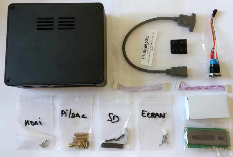
Delivery Contents:
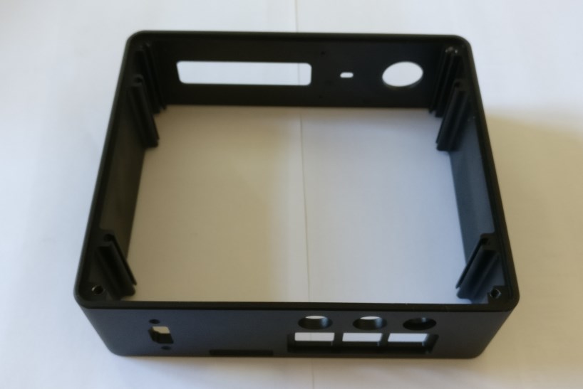
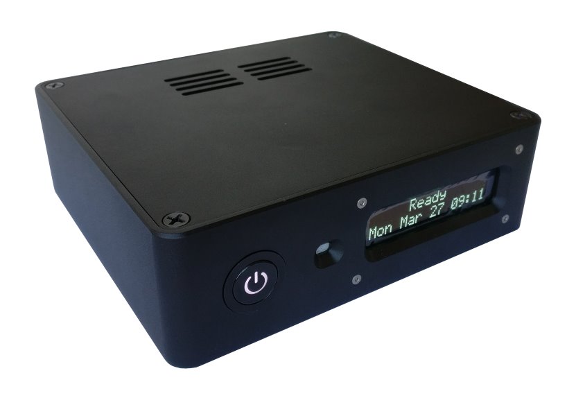
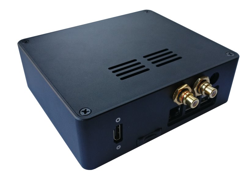
- RaspDAC case
- HDMI adapter cable
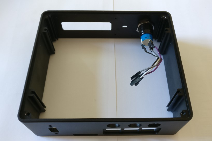
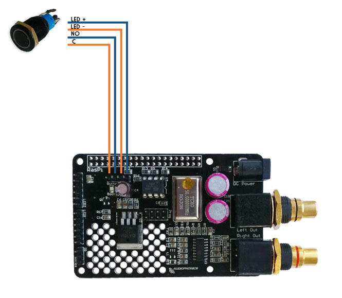
- LED Power Button
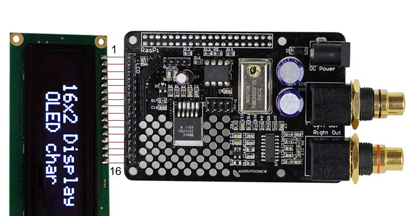
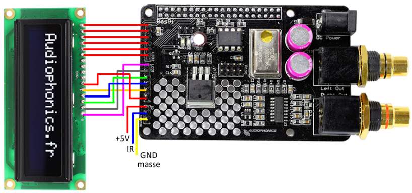
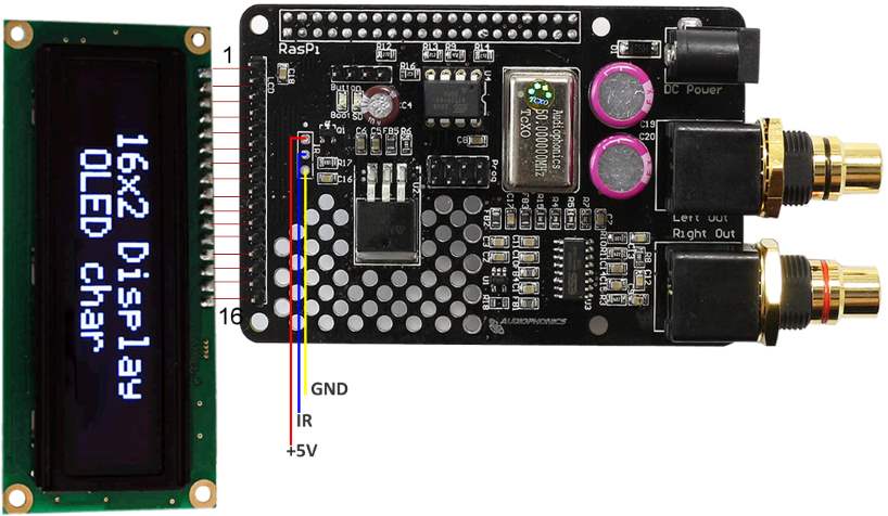
- 2x connection cable for the display
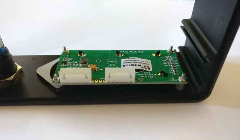
- Winstar OLED display
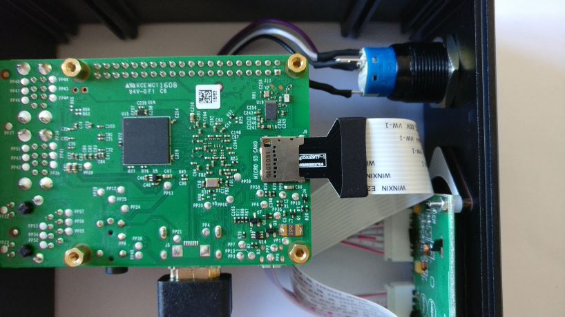
- Micro SD-card adapter cable
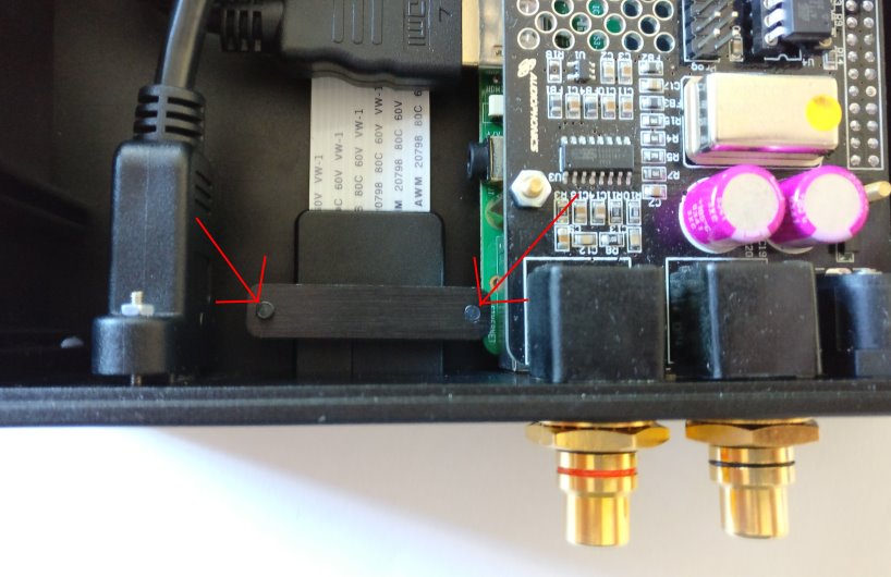
- mounting material for the HDMI adapter cable
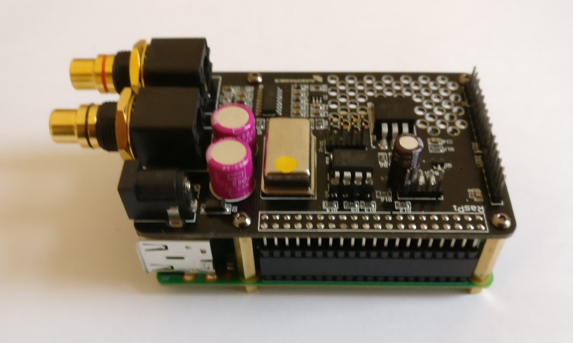
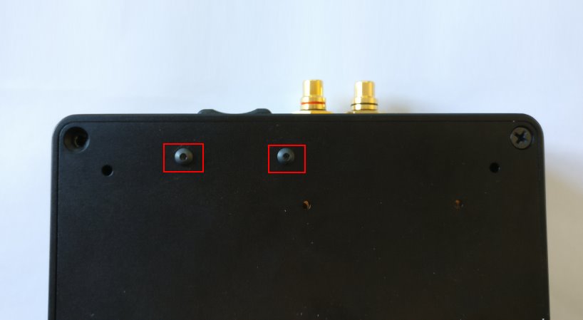
- mounting material for the Raspberry Pi/DAC
- mounting material for the Micro SD-card adapter cable
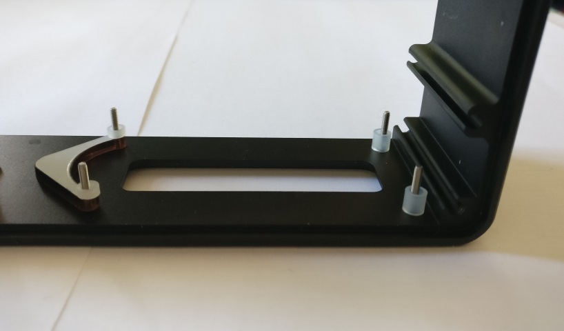
- mounting material for the OLED display
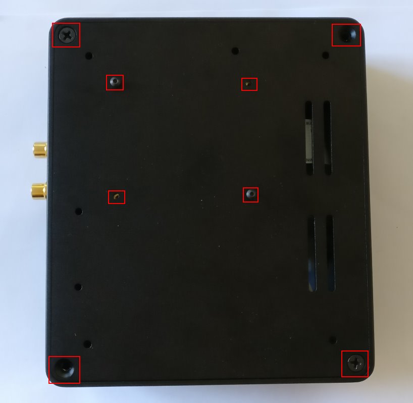
- 4x nonslip rubber feet