Max2Play Home › Forums › Max2Play on Raspberry PI › [SOLVED] No sound from HiFiBerry Digi+ Pro (Max2Play "Squeezebox Touch" kit) › Reply To: [SOLVED] No sound from HiFiBerry Digi+ Pro (Max2Play "Squeezebox Touch" kit)
Hi Ronald
I got a warning saying something was wrong with my sd-card when inserting it into my Windows PC, and was encouraged to run a check of it. I chose to ignore it, I don’t know if there’s something special about how it is formated for the raspberry pi? Was still able to read content though, including config.txt which did have the dtoverlay line in this block:
# Enable audio (loads snd_bcm2835)
dtparam=audio=on
gpu_mem=128
dtoverlay=hifiberry-digi
lcd_rotate=2
It did however also have the line for onboard sound included which the page you link to tells me to remove. So I have now out-commented the dtparam line.
The change does not seem to do any harm, but still no life from soundcard.
Regarding trying the other stuff you suggests, I think I will continue the path started. At least until I give up 🙂
The kit I purchased should been a proven combi/setup. However documentation is seriously lacking.
The guide we have only tells how to setup with a HiFiBerry DAC+ light (not for my Digi+ Pro). For powering DAC+ the guide shows a setup like this:

explaning the setup with this comment:
Since the two peripheries, screen and sound card, both need a lot of juice to run properly, we need to give the sound card an additional power source in the form of the 5 volt connector on the touchscreen. However we cannot connect the two yet since the connectors on the sound card are only for the Raspberry Pi.
That is why we need to solder a little line of five connectors onto the top of our sound card. We just need two connections for the power supply, the first and third hole, so we only need to solder in two places. Once those two are rightly connected and sit strong on the sound card, we need to bend the connectors a little in order to not have them stick out in our case.
Now that this new ridge is added and conformed to the rest of the system, we just need to connect the two cables and all the hardware is in place.
As you see on the photos of my setup (first post and just below here) we have also added the line of five connectors on my Digi+ Pro card, but were unsure which pins was correct to connect on the Digi+ Pro card, since layout seems very different from the DAC+. So we ended out with alternative way shown on photo in first post.
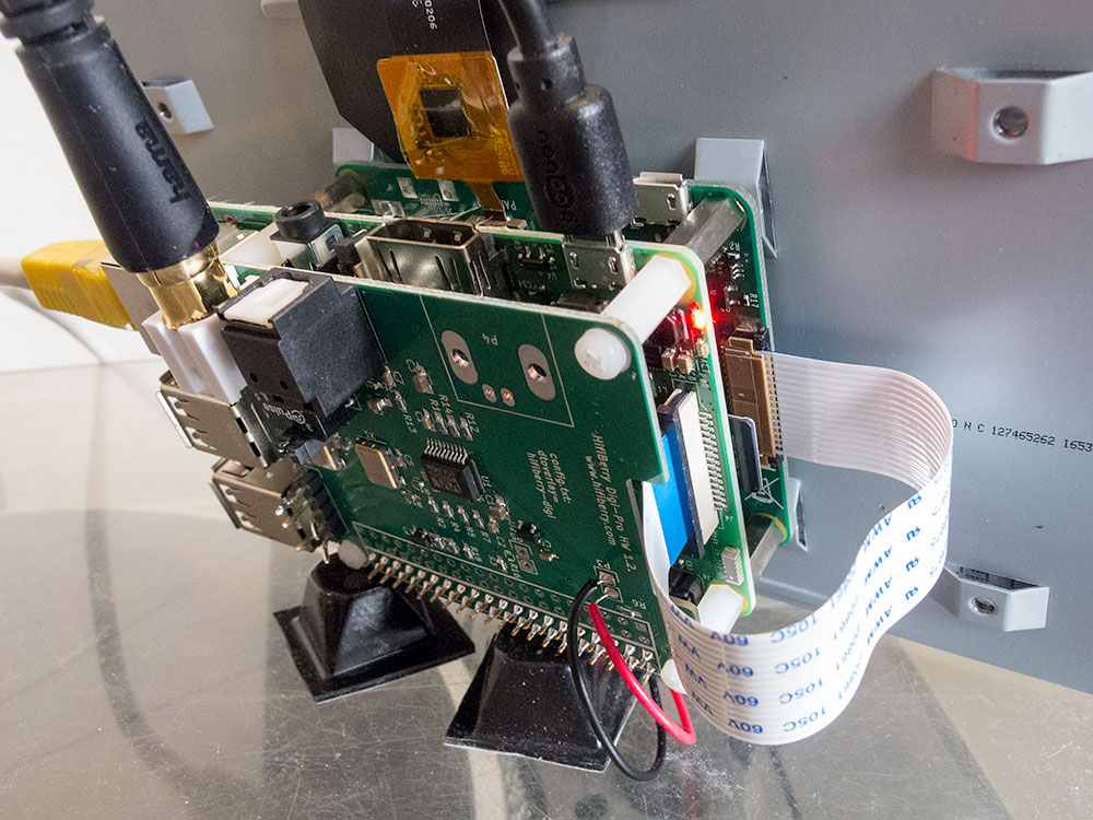
What we really miss is some documentation on the Digi+ Pro card, especially the group called P6. But we haven’t been able to find it anywhere.
Our alternatively approach came from this page:
https://support.hifiberry.com/hc/en-us/articles/213227645-Digi-Pro-power-separately-from-the-Raspberry-Pi
The page tells you how you can power the digital part of the board independently. I guess we assumed that you can also power the whole board from P3 if you just leave the resistor R3 where it is. But that assumption might be wrong?…
-
This reply was modified 9 years ago by
StigN. Reason: minor