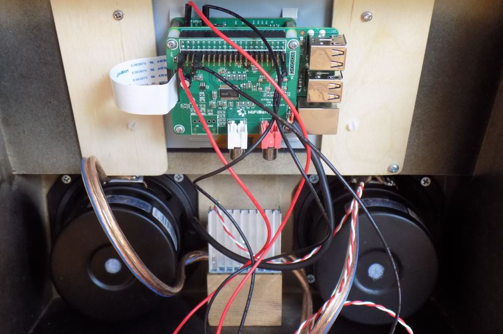
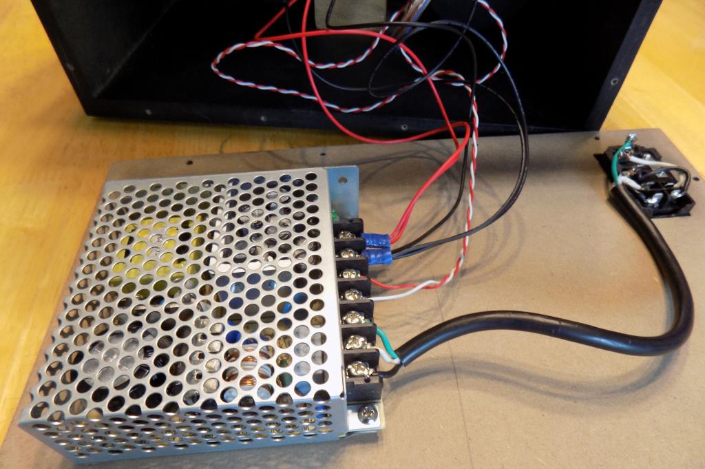
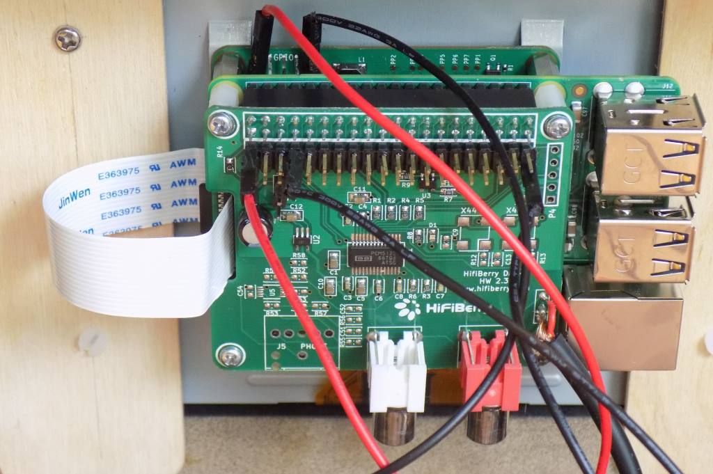
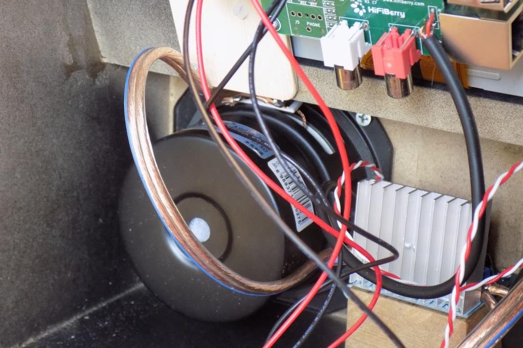
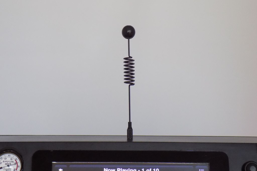
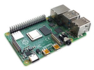
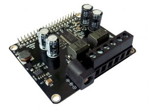
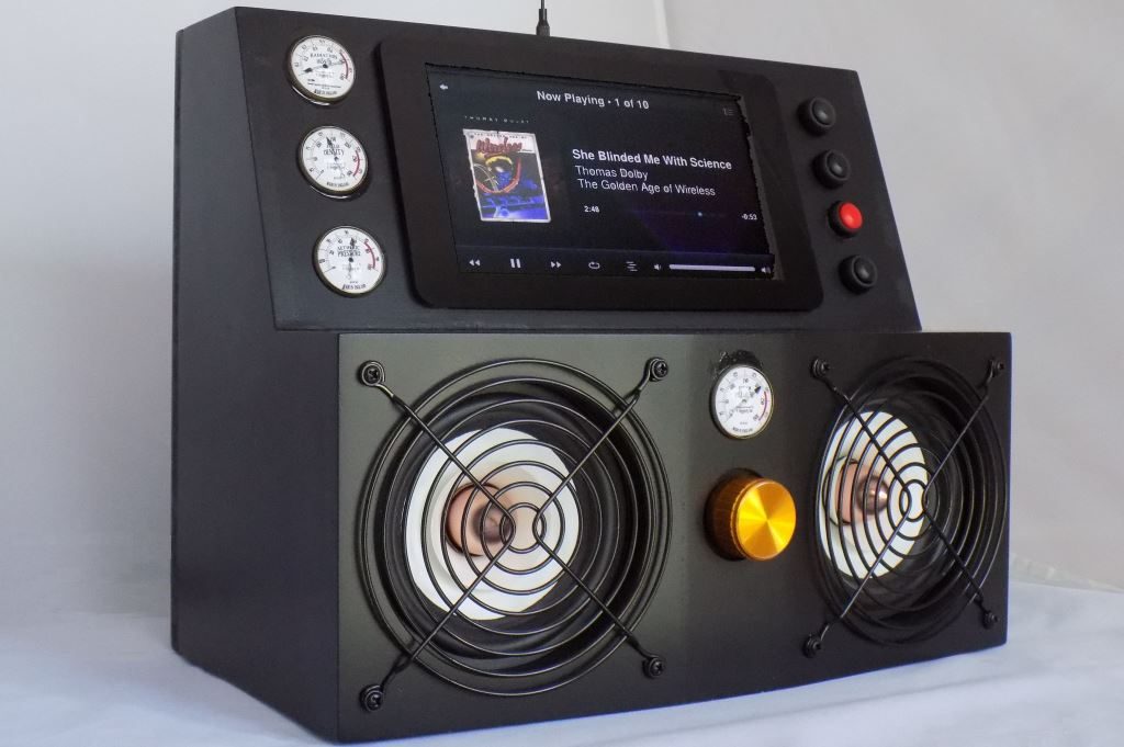
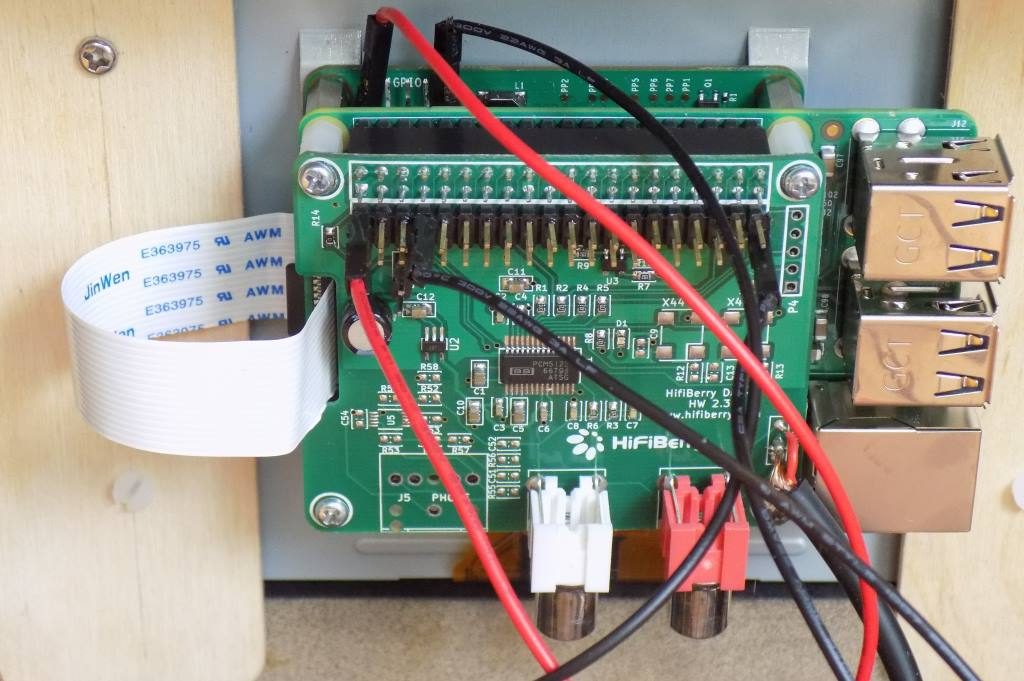
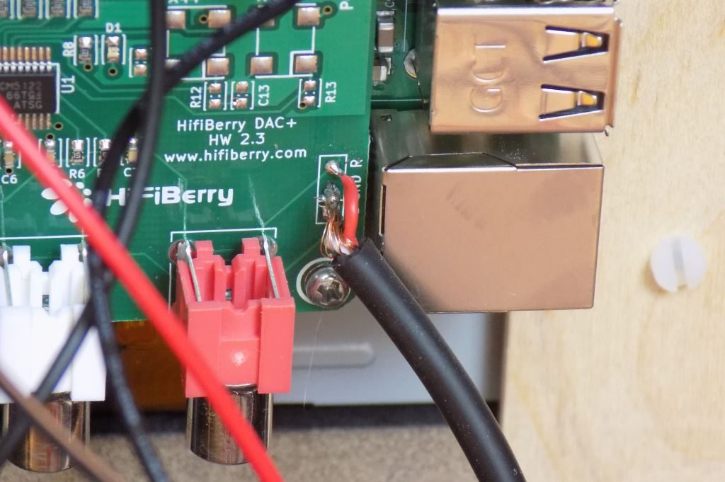
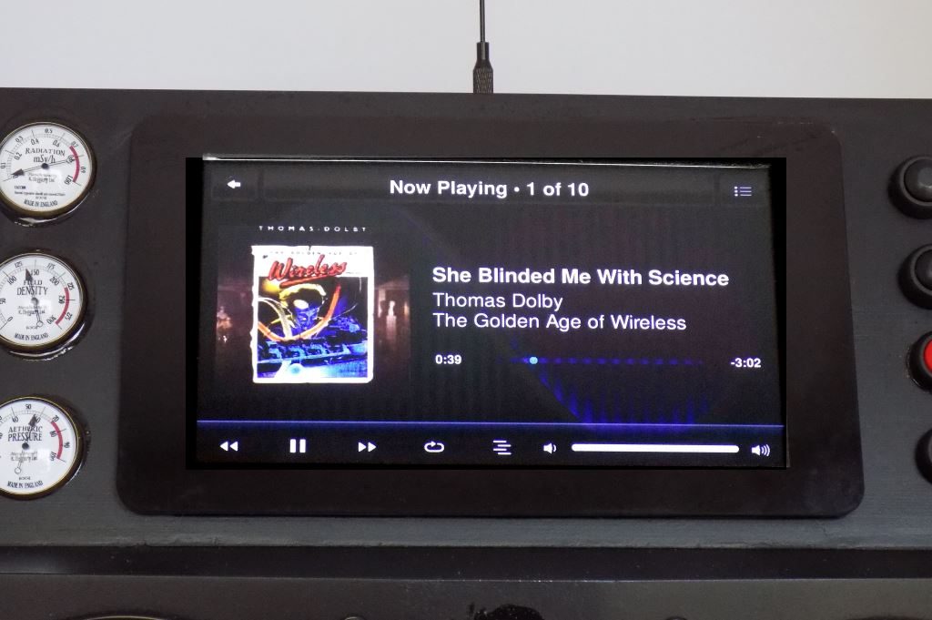
Hi guys, this article is a big one! It is Joe Jaworski’s Jetsons Music Box, a fantastic piece of DIY production utilizing the some of the best features of Max2Play and the high-end sound of the HiFiBerry DAC+ sound card. I hope you enjoy reading the article as much as I did collaborating with Joe on it! Heiner from Max2Play My motivation for building this project comes from the fact that the Logitech Corporation discontinued its Squeezebox and UE Radio lines several years ago. I have been a big fan of this open-source streaming protocol since the original SlimDevices products of 2001. I have many Squeezebox players throughout my home. I have looked at more modern alternatives but have not found any that meet my needs. One day I saw a screenshot of a Linux based streaming player on the web. It looked amazingly similar to my Squeezebox Touch screen. I was very excited that it was now possible to build my own Squeezebox player from scratch. I wanted a streaming player that was stand-alone (had its own speakers/amplifier + wifi streaming) rather than having to add speakers or plug it into an existing receiver. It needed to be somewhat portable where I could carry it to the backyard for a barbeque or with a get together with friends. My first design flirted with the looks of those large “Boom Boxes” of the 1980’s. But I did remember how ugly they were, had terrible sound quality, and were large and bulky. I also looked at present-day electronics enclosure design. But everything looks similar and is not very exciting (Think of cars today made by different manufacturers- they somewhat look all the same). Then I came upon the “Atomic Age” design. In the 1950’s and 1960’s, the world was abuzz with the future. In Los Angeles, California USA a new type of “space age” looking buildings began to pop up everywhere. It was called “Googie” (not to be confused with Google) architecture. Movies and TV shows featuring space travel, alien invaders, and the like were very popular then. Most people remember seeing the cartoon series “The Jetsons” which came out in the same period and took the atomic age design to new heights. So I thought why not provide music and at the same time create a conversation piece? I am not very good at carpentry. So I had a friend of mine build the box. I did not give him many instructions, we just went over the concept and he took it from there. The design places two 4-inch speakers slightly angled away from each other (for better stereo separation). All the electronics (except for the stereo amplifier) is in the upper section attached to the back of the display. The main electronic components are the Raspberry PI-3, HifiBerry DAC+, and the Max2Play software. The software is more than just “glue” code. It is a complete customized Linux operating system dedicated to playback of media with many packages to allow extensive support and customization. My project uses the SqueezeLite client with Jivelite, but Max2Play is capable of HD video, other streaming protocols (such as AirPlay) and many more features that I’m not using. As the basis for my project I used a Raspberry Pi 3. You can use other Pi models, but I chose the Model 3 to avoid having to use a USB WiFi dongle, and to take advantage of its greater speed. The display I used is the official Raspberry Pi 7-inch Touch Display. The Max2Play software supports this and many other displays so you can use other brands as well. During testing, I hooked up a PC video monitor to the Pi and it automatically switched from touch display to PC monitor. The display controller (attached to the back of the display screen) is designed so that the RPi is attached with stand-offs to the top of the board. Then the HifiBerry DAC+ board is plugged in on top of the RPi. It makes for a neat installation as the three boards are neatly stacked and firmly connected to one another. The RPi and the 7-inch display require lots of power. Most standard USB chargers/adapters won’t cut it. I discovered that it’s not just the USB power supply itself, but the small thin wires (typically 28 AWG stranded wire) used in most USB cables. I was able to find and purchase some USB cables that used 18 AWG wire for power and ground, and many of the USB power supplies that failed before would now work with the thicker wire USB cable. I still didn’t want to take a chance on inadequate power. So I stopped using the micro-USB connector altogether and ran two +5V lines and three ground lines direct from the power supply to the boards. You can see these wires in the photo as individual red and black wires plugged into the power pins of the display and HifiBerry board. In order to make this work, I needed to solder another 40-Pin header to the HifiBerry in order to access the power and ground pins to connect to my power supply. I used a switching power supply, the Meanwell RD50A dual output DC power supply. It can work from 110VAC to 250VAC at 50 or 60 cycles. It is quite small for its power rating, measuring 3.9 x 3.8 x 1.4 inches (10cm x 9.5cm x 3.5cm). I know, the audio purist would say to use only a linear power supply, but during my testing there was no audio noise or distortion that I could hear. Besides, I did not want to deal with excess heat and possibly have to add a fan because linear power supplies run hot. The Stereo amplifier board needs +12VDC with everything else using +5VDC. The RD50A offered more current than I needed, but I couldn’t find a smaller power supply with dual output like this one. As a safety measure, it is wise to protect any open frame power supply with a fuse and cutoff switch. As shown in the photo, the back of the case contains a combination fuse holder, on/off switch, and IEC cable connector. I used a 250V 1 amp fuse which should be more than adequate. Be VERY careful when working with the cover off as mains voltage is exposed at the switch contacts and the AC screw terminals of the power supply. The HifiBerry DAC+ board is essentially plug-and-play. However in my case, what I had to do is make some modifications. As mentioned earlier, I had to add a second 40-pin connector in order to satisfy my power supply hookup requirements. Secondly, I needed an audio cable with dual RCA male jacks on one end and a right-angle 3.5mm stereo jack on the other. This is because the amplifier board used a 3.5mm input instead of RCA style. I only needed a cable that was 10 cm long or less. I did not want to roll up a longer cable inside the box. So I opted to cut the cable and solder it directly to the HifiBerry board as shown in the photo. Fortunately, the HifiBerry provided solder pads in parallel with the RCA stereo output jacks. Since this was a stand-alone player, I needed to add a stereo amplifier. I needed something small and low cost. I knew of the TDA7297 chip (15W x 2 channel output) which was cheap and easy to work with. Rather than build my own, I found a complete stereo amplifier on Ebay based on the TDA7297 that was less than $7 USD. As shown in the photo it is mounted on a block of wood between the speakers where the built-in volume control shaft could protrude through the front panel. While the touchscreen is also capable of changing the volume, I just find it easier to twist a knob rather than sliding a finger across the display. The heatsink is very adequate. Even at high audio volume, it only gets slightly warm. The speakers are 4-inch Audio Labs full range 4-ohm speakers. You could use any type of speakers for this project, either 4 or 8 Ohm impedance. I had tested the RPi board and display with an SD card containing plain old Raspbian to make sure that the hardware was okay. The display, touch, and everything else worked fine. I couldn’t test the HifiBerry without drivers, but it was installed and didn’t smoke so that’s a good sign! Note: I already have the Logitech Media Server running on my home Linux server. You will need the Logitech Media Server running somewhere on your network so you can stream music to any Squeezebox player. (One-Click Installation of version 7.9 in Max2Play on Raspberry Pi) Here are steps I went through to set it all up the first time: Step 1: You need to attach an Ethernet cable to the RPi for initial setup. There is a way to set up without it using a certain brand of router with Max2Play, but I didn’t have that hardware. (WPS on your router or Access Point Autostart since Max2Play 2.44) Step 2: The first thing I experienced was the display was upside down. This was my fault, as I originally mounted the display that way to make cable access better (and actually, I mounted it right-side up according to the display spec). Step 3: Once booting was complete, I needed to find the IP address of RPi assigned by DHCP. The http://max2play URL did not work for me, possibly because I have uPnP turned off on my network for security reasons. Anyway it was easy to find either by looking at my firewall log or my router’s DHCP assignments. You could also use one of those free IP Scanner programs that list all your active IP addresses. Step 4: Once I had the IP, I used Putty to login to the RPi via SSH and changed the /boot/config.txt file by getting rid of the “lcd-rotate” line (You can also use the RPi-Display Plugin in Max2Play). Then another reboot. The display was now right-side up. Step 5: Next thing I did is setup WiFi, so I can pull the Ethernet cable. Rebooted, found the new IP, and was ready to go. Step 6: Now I entered the new Wifi IP address into my browser (in my case, http://192.168.0.112) and voila! The Max2Play web server home page appeared. Interesting that I never had to enter the IP address of my Media Server computer, as Max2Play found it on its own. Step 7: You need to do a few maintenance things before you’re ready to go: Step 8: You should deactivate Shairport’s Autostart. (You can also use the Automatic Audio-Switch) Next step is for the HifiBerry card. You need to download and install the Max2Play HifiBerry plug-in, then select the board type (This now possible on first boot, without any plugin). You won’t have any sound until you do this. A word of caution: The Max2Play website looks almost identical to the local max2Play webpage in your RPi. This can get very confusing, especially during plug-in installations when you have two browser windows opened with each. I found that things went a lot smoother once I realized this. You should now be able to reboot and search through your music using the display and touchscreen and play to your heart’s content. When I streamed my first song, I noticed the sound was a little boomy (muddled bass and lack of midrange). I had thought about adding tone control or a Loudness circuit, and then realized there was equalization available. It did not work for me. I found a website that explained how to configure Max2Play to make the equalizer work through the HifiBerry card. It worked great and so glad to have a software solution. In keeping with my Atomic Age theme, I needed to add some embellishments to enhance the look. The Jetsons home appliances were always covered in brightly colored buttons (no one back then imagined touch screens, like on your microwave oven). So I added a row of buttons (3 black, 1 red). I thought about hooking these to GPIO pins and have them perform some function, but the Max2Play software brings everything to the touch screen. Adding the buttons was an afterthought. I didn’t want to drill holes after the box was painted. I wound up cutting off the bottom half of the SPST switches with a hobby rotary tool and gluing the top part to the front panel. Next I added some analog gauges. I guess folks back then did not predict the coming of LED or LCD 7-segment displays. So a mixture of a few faux analog gauges helped enhance the look. Finally, I wanted to add an antenna similar to what was on Elroy’s hat or Astro’s tail in the cartoon. I bought a real WiFi extension antenna and cut it down to highlight the center coil. I went to a craft store and purchased a small wooden ball and painted it black. The ball was glued to the top of the antenna as shown in the photo. As a last step, you need to install the Write-Protect plug-in. Linux, like most operating systems, requires a graceful shutdown in order to safely close all open logs and files. Simply “pulling the plug” or having a brief mains power failure will eventually corrupt your SD Card. The plug-in is easy to use as you can switch from Read-only to R/W operation from its webpage. You will use this quite frequently during the first days of use as you further tweak the Max2Play settings to your liking. Joe Jaworski is an electronics engineer with 35 years’ experience in the industry. Most of his career was spent in California USA, where he worked in integrated circuit design and microcontroller embedded firmware. He now runs a company and website that provides services to hobbyists, makers, and R&D firms that need short run PCB fab and assembly, PCB layout and design, and a variety of other services at
I contacted Joe a few weeks ago after seeing his project in a contest when I thought this has to have been made with Max2Play. He was fully on board and wrote this great, detailed report on how he got the idea for the box and how he was able to fully realize it thanks to the powerful components and a little bit of our software.The Jetsons Design
The Enclosure
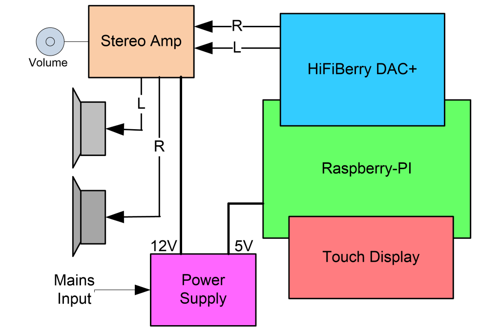
The enclosure is made from MDF (Medium Density Fibreboard). It is 0.5 inches (13mm) thick. As opposed to plywood, MDF is a good material to use for speaker cabinets as it doesn’t emphasize or decrease some audio frequencies as other woods can.The Guts
Power Supply Issues
HifiBerry Hookup
Stereo Amplifier
First Boot
Audio Quality
Bells and Whistles
Write Protect
BIO
“The Jetsons” Music Box by Joe Jaworski
0 Comments


